Msd 3 Step Module Wiring Diagram
Msd 8737 Rpm Module Selector Installation Instructions Jegs
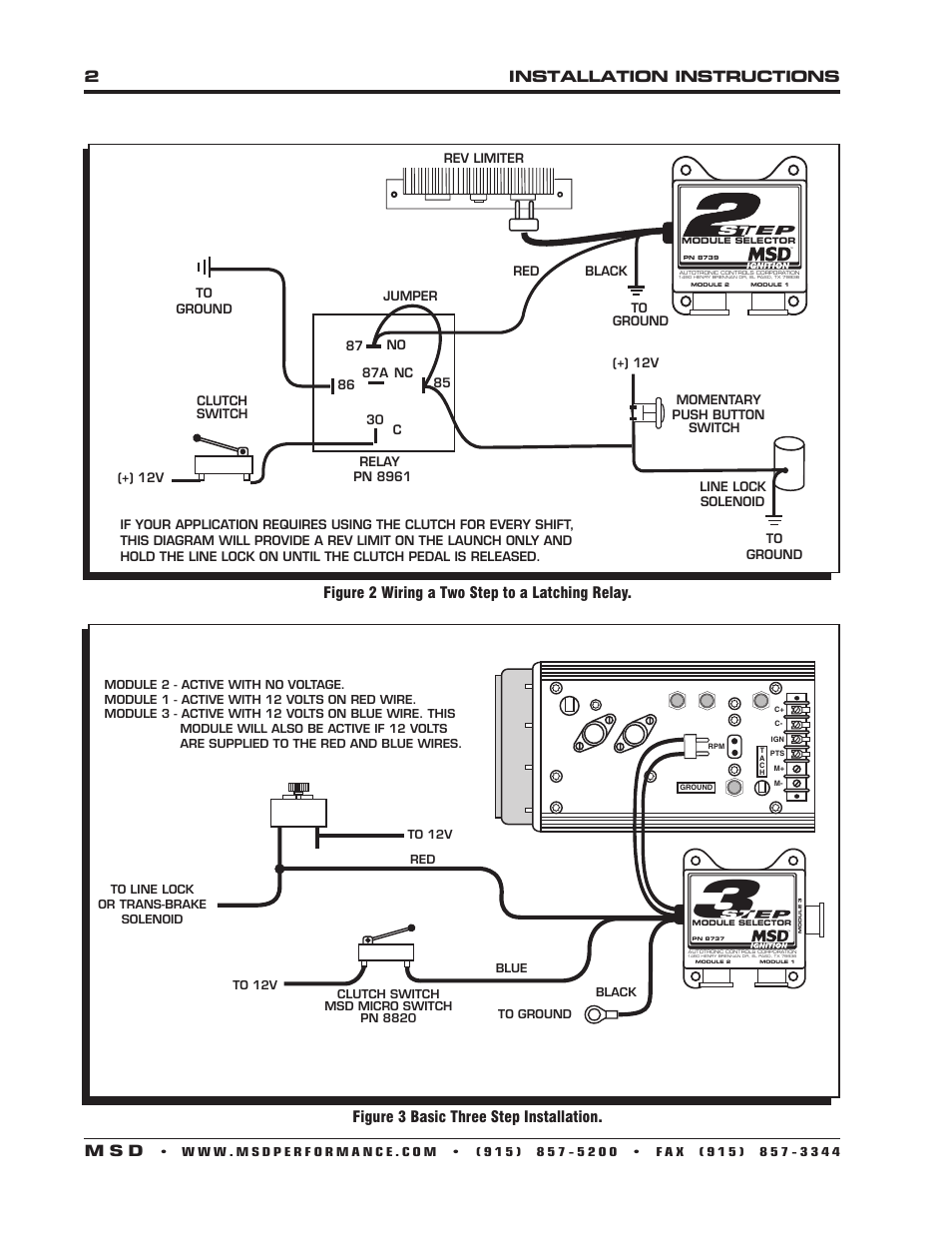
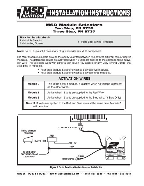
2installation Instructions M S D Figure 3 Basic Three Step Installation Figure 2 Wiring A Two Step To A Latching Relay Msd 8739 Two Step Module Selector Installation User Manual Page 2 4 Original Mode
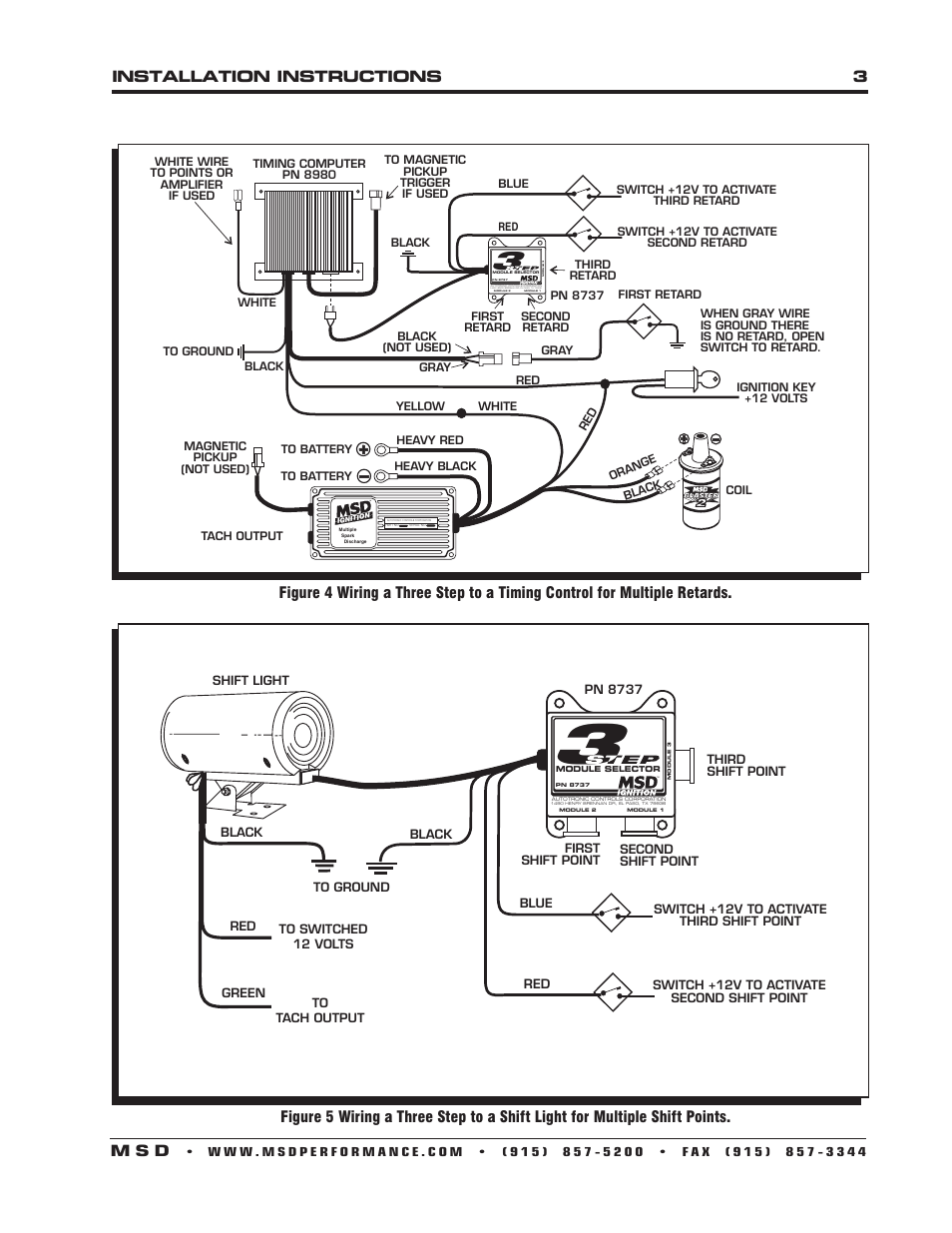
Installation Instructions 3 M S D Msd 8739 Two Step Module Selector Installation User Manual Page 3 4 Original Mode

Diagram Msd 8861 Wiring Diagram Hei Full Version Hd Quality Diagram Hei Pdfxstolpg Dolcialchimie It

Pin On Wiring Diagrams Gallery

Chevy Ignition Coil Distributor Wiring Diagram In Addition Diagram Msd Automotive Care Automotive Illustration Diagram

Page 2 installation instructions rev limiter step module selector pn 8739 black autotronic controls corporation 1490 henry brennan dr el paso tx 79936 module 2 module 1.
Msd 3 step module wiring diagram.

The Msd 8 Plus Ignition Produces The Same Extreme Output Of The Original 8 Series Yet Is Now In A Smaller Housing With Improved Eff Ignite Msd Ignition System

10 1997 Toyota Camry Electrical Wiring Diagram Wiring Diagram Wiringg Net In 2020 Electrical Wiring Diagram Electrical Wiring Repair Guide

Wiring Diagram For A Yamaha Warrior 350 And Electrical Diagram Diagram Diagram Design

How To Test The Gm Ignition Control Module 1995 2005 Auto Repair Car Mechanic Automotive Mechanic

Allstar Performance Msd 6 Series Ignition Box Mounting Plate All81330 Car Parts And Accessories Race Car Parts Drag Racing Cars

Ad Ebay Msd Ignition 75591 Programmable Rpm Trans Shifter In 2020 Shifter Msd Transmission

Automobile Starter Motor Working Principle Google Search Starter Motor Motorcycle Wiring Automotive Repair

1979 F 150 Wiring Diagram Ford Truck Enthusiasts Forums Ford F150 F150 Ford Lightning

Alkydigger Msd Ignition Timing Supercharger

High Performance Ignition Systems Pdf Ignition System Ignite High Performance

Pin On Stuff To Buy

Msd Atomic Efi Airforce Intake Manifold Black Gm Ls1 Ls6 Ls2 27023 Black Air Force Msd

Putco Pure Led Third Brake Lights Free Shipping F150 Car Emergency Kit Automotive Accessories

Pin On Tire Accessories Wheels Tires And Parts Car And Truck Parts

Msd Atomic Efi Airforce Intake Manifold Black Gm Ls1 Ls6 Ls2 27023 Black Air Force Msd

Pin On Deals Spark Plug Wires

There Are Two Different Ecu Connectors For The 4l60e The Green Connector Is From 1999 2005 Wh 4l60e Transmission Rebuild Chevy Transmission Automotive Repair
Pin On Wikidiy Projects
Https Encrypted Tbn0 Gstatic Com Images Q Tbn And9gcrhi9hdqm Qtjphuscn1fetwyghiixxhfsg 4zybqqhiyz6d0ce Usqp Cau

Pin On Engines And Components Car And Truck Parts

1965 Ford Galaxie 500xl W166 Indy 2014 In 2020 Ford Galaxie Galaxie Custom Car Interior

The Msd 8 Plus Ignition Produces The Same Extreme Output Of The Original 8 Series Yet Is Now In A Smaller Housing With Improved Eff Ignite Msd Ignition System

Msd Ignition Wiring Diagram Two Step Wiring Diagram Mobile Mobile Valhallarestaurant It
Https Encrypted Tbn0 Gstatic Com Images Q Tbn And9gcrour6qopfw Qhykm Bopjogyramsaza4qlgpgoojq 3b7qqs1 Usqp Cau
Source : pinterest.com
